Locking differentials are one of those upgrades that make a real-world difference the moment you need them. Done right, they won’t just help you conquer obstacles – they’ll give you peace of mind in terrain where traction is anything but guaranteed.
Step-by-Step Guide to Locking Differential Installation
Marking the Bearing Caps
With the final drive assembly securely clamped in a bench vise, the first step in your locking differential installation is to mark the bearing caps. These caps are side-specific and must be reinstalled in their original positions, so use a punch to create identifying marks on both the differential carrier and the corresponding bearing caps on each side.
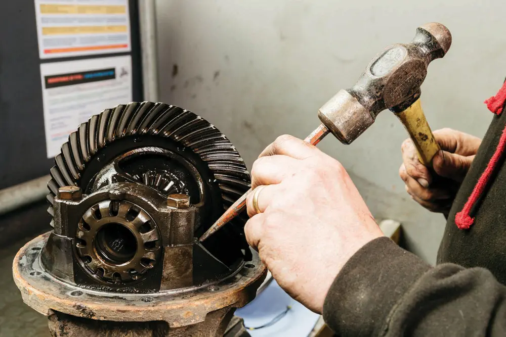
Removing the Bearing Caps
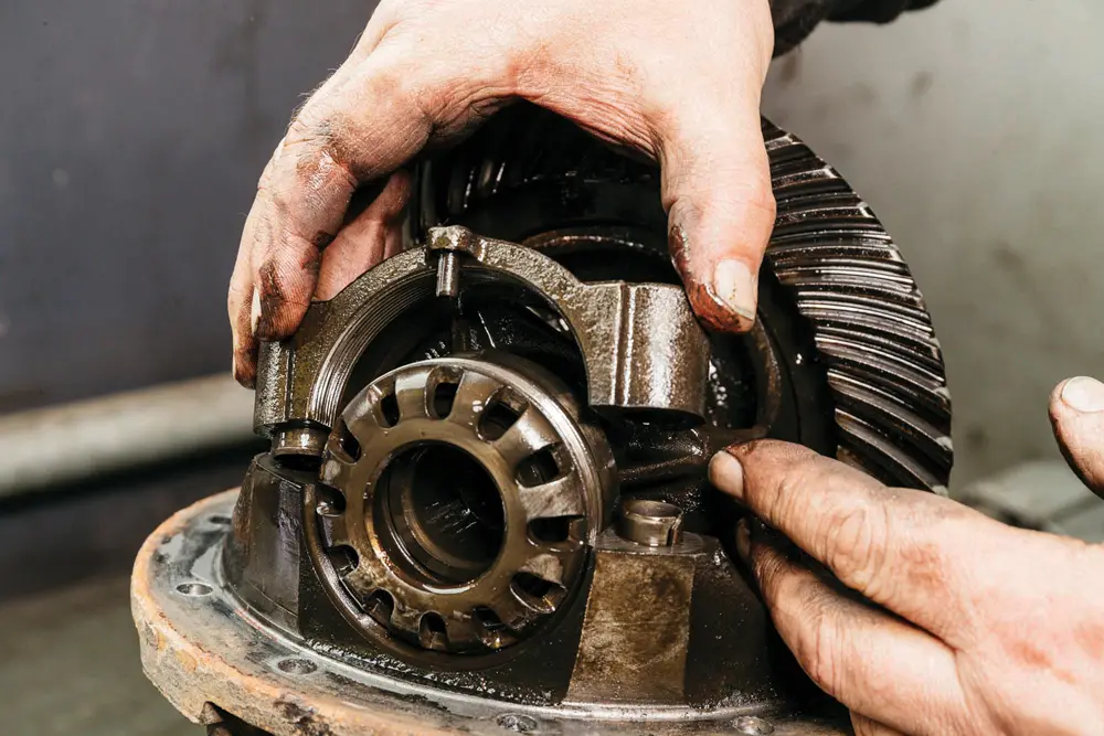
Carefully remove the bearing caps from the carrier. Tap the locking spring pin (located at the top center) outward until it is flush with the cap surface. This prepares it for reinstallation later—just be cautious not to damage the pin during removal.
Lifting the Differential Assembly
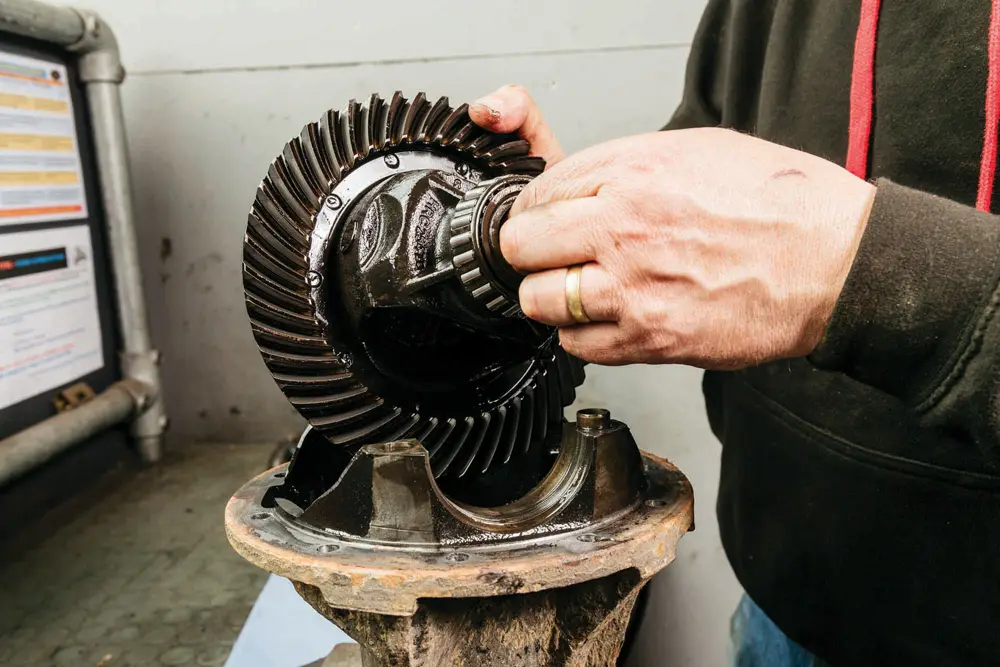
With the caps off, lift the differential assembly out of the carrier. For this locking differential upgrade, only the differential unit itself will be replaced. You’ll need to separate it from the ring gear—but there’s a specific technique required for that step.
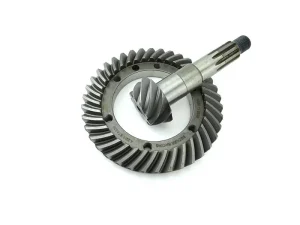
Removing the Ring Gear
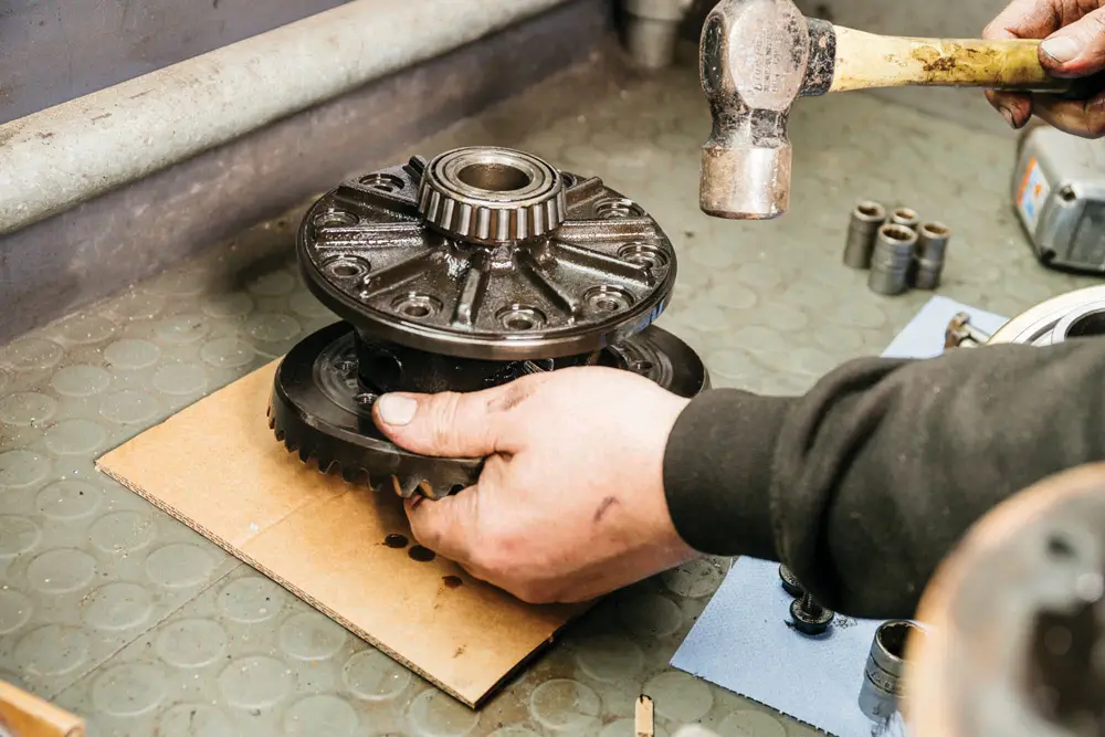
Loosen and remove the ring gear bolts. Then, gently tap the ring gear to separate it from the original differential. It’s a tight, interference fit, which presents a challenge during the reassembly process.
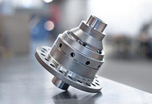
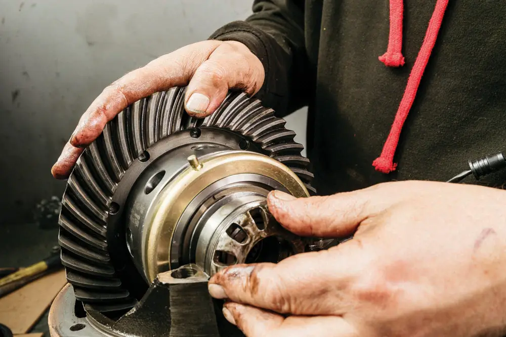
Old vs. New Differential
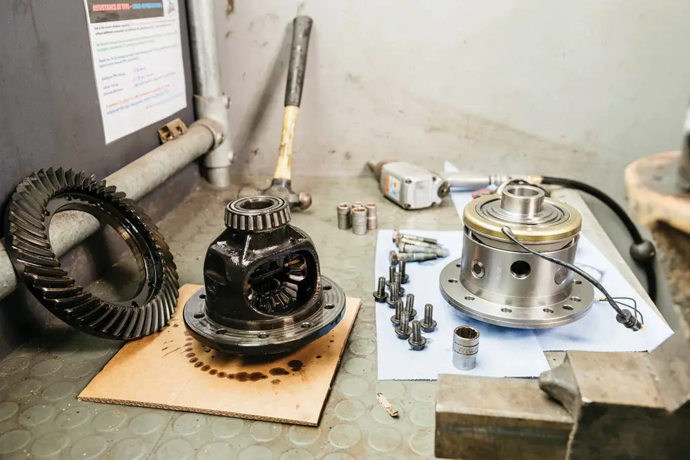
Here’s the comparison: the factory diff and the new locking differential. It’s a direct swap in terms of fitment, with the addition of a power feed for activation. However, at this stage, the ring gear won’t yet slide onto the new differential housing.
Removing the Electromagnetic Clutch
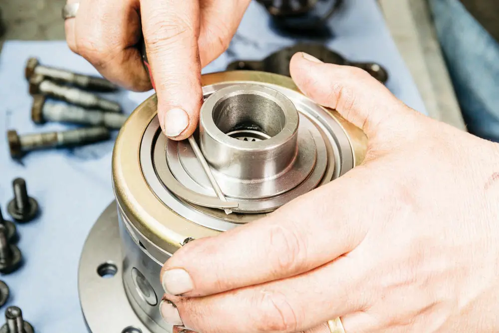
Before proceeding, wear eye protection. Remove the electromagnetic clutch, which is held in place by a belleville spring. Use a flathead screwdriver to gently pry out one edge, then rotate it off to fully detach the clutch.
Prepping the Ring Gear
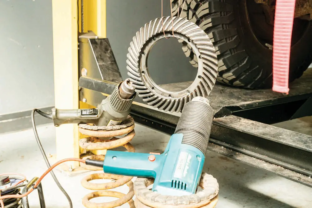
Clean the inner surface of the ring gear thoroughly using brake cleaner, then let it dry completely. To prepare for reinstallation, heat the ring gear to slightly expand it—two heat guns for about 15 minutes typically works well.
Installing the Ring Gear
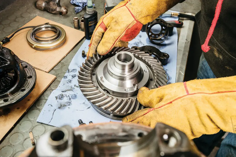
After cleaning the ring gear bolts and applying thread locker, put on welding gloves for safety. While the gear is still hot, slide it over the new locking differential. If properly aligned, it should fit easily.
Securing the Ring Gear
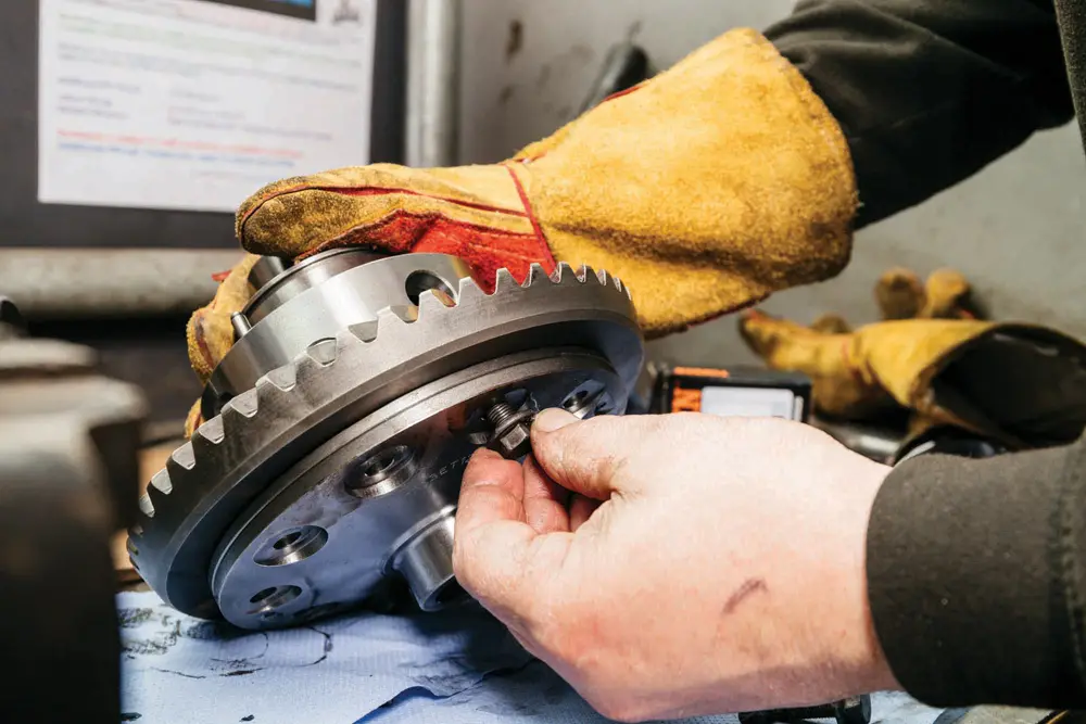
Let the gear cool down, allowing it to shrink and seat firmly on the new differential. Begin by installing two opposing bolts to center it, then secure the remaining bolts. Torque all fasteners to 70Nm to ensure a proper hold.
Reinstalling the Clutch Mechanism
Finally, refit the electromagnetic clutch onto the new differential. Reinsert the belleville spring by easing one end into its securing groove, then working around the edge to fully seat it. With this step completed, your new locking diff is nearly ready for final assembly.
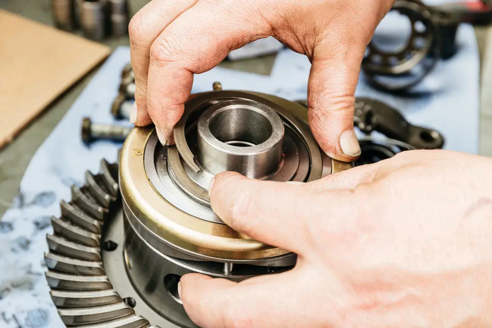
Installing New Bearings
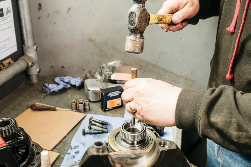
As part of best practice in any locking differential installation, it’s strongly recommended to use brand-new bearings from a reputable manufacturer. Gently tap the bearings into place using a soft punch and hammer, working evenly around the center to ensure a proper and secure fit.
Drilling for the Power Supply
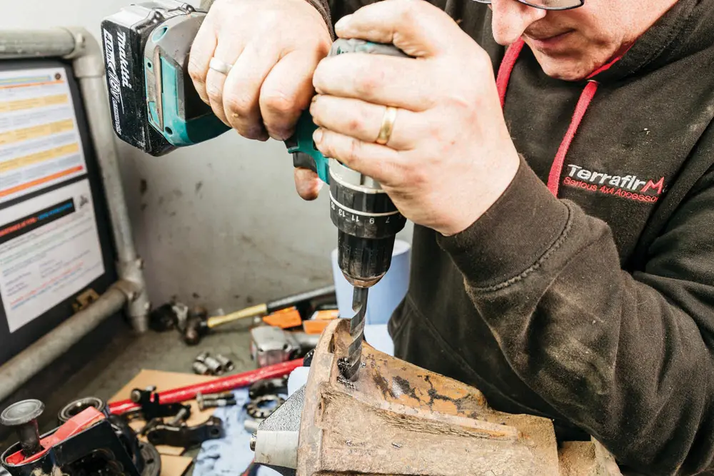
The differential casing requires a 12mm hole to route the locker’s power wire. Start by marking the drill point with a center punch, then begin with a pilot hole. Gradually increase drill size until you reach the required 12mm diameter for a clean and accurate cut.
Preventing Contamination
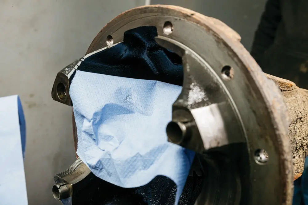
While drilling the casing, it’s critical to prevent metal swarf from entering the housing. Use a paper towel or wipe to catch debris at the point of drilling, and carefully clean the area afterward to remove any remaining particles.
Routing the Wiring
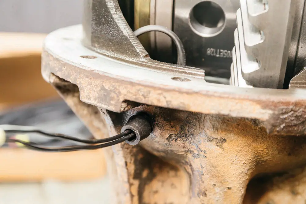
Feed the power wire through the newly drilled hole and install the rubber grommet into place. The fit may be tight—use care and avoid tearing the grommet. A small amount of silicone sealant can be applied around the center to ensure a secure and waterproof seal.
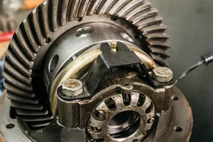
Reinstalling the Differential
Once all components are clean and debris-free, carefully lower the new locking differential with the crown wheel into position, seating it onto the carrier bearings. Place the bearing caps over the assembly, but do not torque them down just yet.
Setting the Backlash
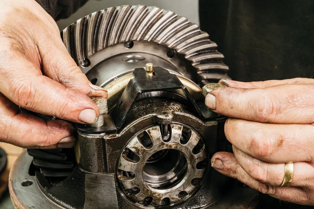
To set the correct backlash between the pinion and crown wheel, tighten the bearing adjuster by feel or measure with a dial test indicator (DTI)—aiming for a target of 0.10mm. Once properly adjusted, tap the lock pin back into place. The clutch locator bracket should be positioned beneath the appropriate bolt heads.
Final Torque and Assembly
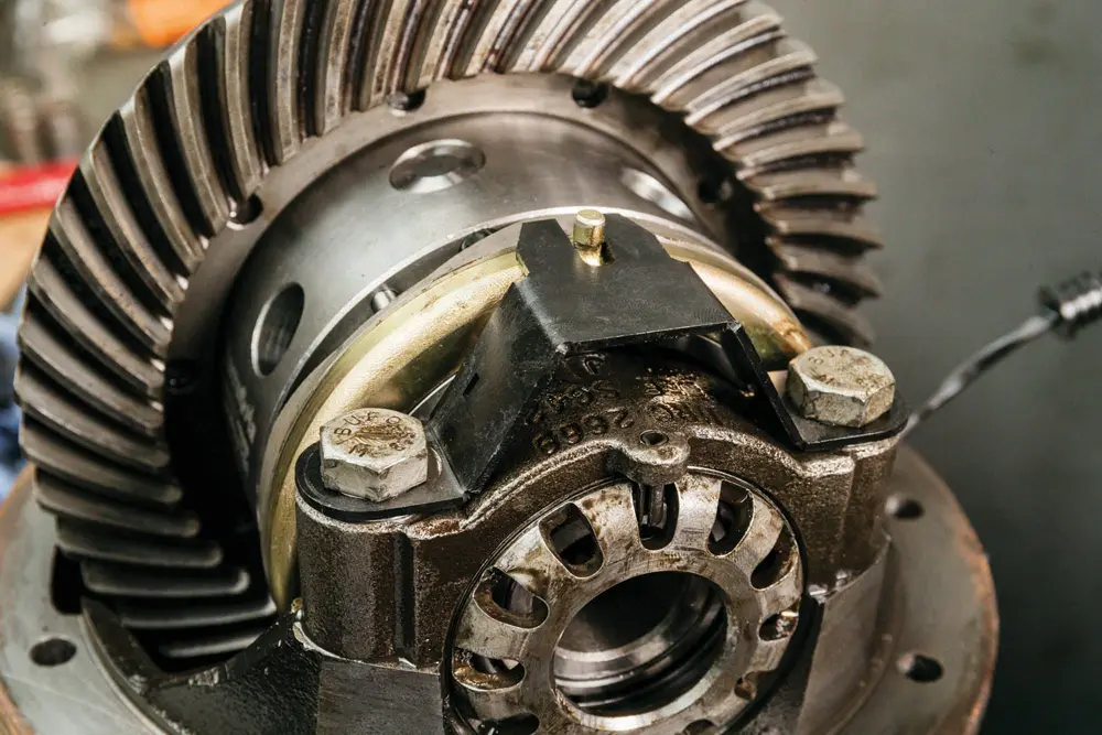
After verifying alignment and backlash, tighten the bearing cap bolts to a final torque of 85Nm. With that, your new locking differential is fully assembled and ready to be reinstalled into the axle housing.
Refitting the diff assembly
Preparing the Axle Casing
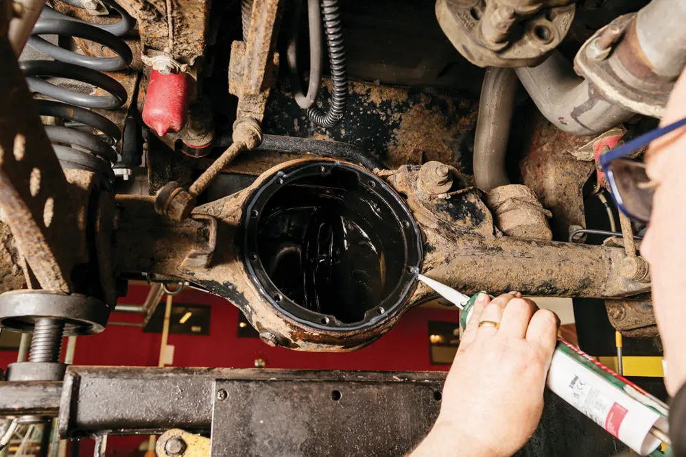
Before refitting the locking differential assembly, thoroughly clean the axle casing’s mating surface. Use a wire brush to remove old sealant or debris, then wipe it clean. Apply a continuous bead of high-quality silicone sealant just outside the bolt holes to ensure a leak-free seal when the diff is installed.
Installing the Differential Assembly
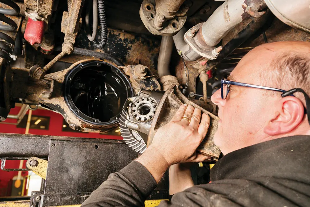
The differential assembly is heavy and awkward to handle, so be sure to get a firm grip on the unit. Carefully lift and guide it into the axle housing, aligning it with the bolt holes. Using a temporary fixing bolt can help keep it steady while you secure the rest of the fasteners.
Securing and Reconnecting Components
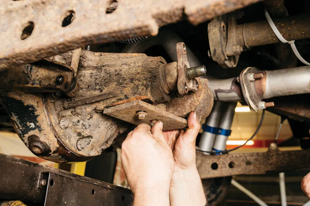
Once in place, tighten all the differential housing bolts evenly. Then proceed to reconnect the propshaft, harmonic balancer, and drop link. Don’t forget to fill the differential with the appropriate gear oil before moving on—this marks the end of the messy part of the job.
Final Reassembly
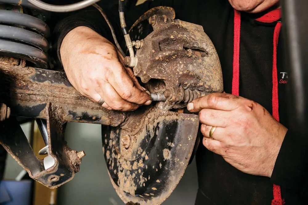
Reinstall the hubs, brake discs, calipers, and road wheels in the reverse order of removal. It’s good practice to apply a small amount of thread locker to the hub and brake fasteners, but never on the wheel studs. Once everything is torqued and secure, your locking differential installation is complete and ready for testing.
Connecting the electrical system
Wiring the Loom
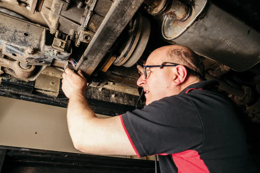
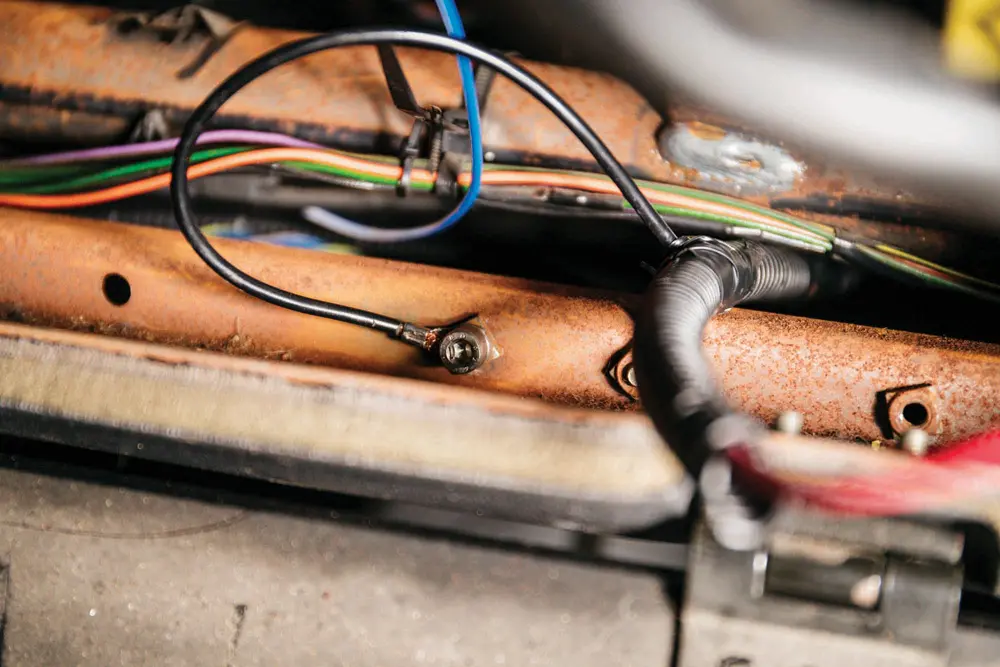
Connect the wiring loom to the locking differential, then carefully route it forward along the top of the chassis rail. Make sure the harness is secured well away from any moving or high-temperature components. Feed the cable through the vehicle’s bulkhead using an existing grommet.
Routing Into the Cabin
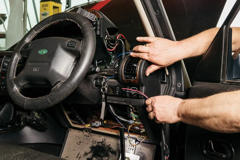
Inside the cabin, you’ll need three key connections: an ignition-live power source, an illumination feed for the switch, and a good ground. The harness should be routed neatly into the vehicle’s fuse box area—such as in a Land Rover Discovery—for proper integration.
Professional Wiring Touch

Adam Luckett from VolksTechnics demonstrates how professionals handle electrical connections. Using a multimeter, he quickly confirms the correct circuits for ignition and illumination feeds, ensuring a clean and reliable setup.
Switch Illumination Source
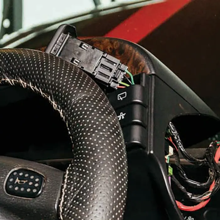
The power supply for the diff lock switch’s illumination is taken from the rear wash/wipe switch circuit located on the dashboard binnacle. This circuit is live when the driving lights are turned on, making it a suitable illumination source.
Creating the Splice
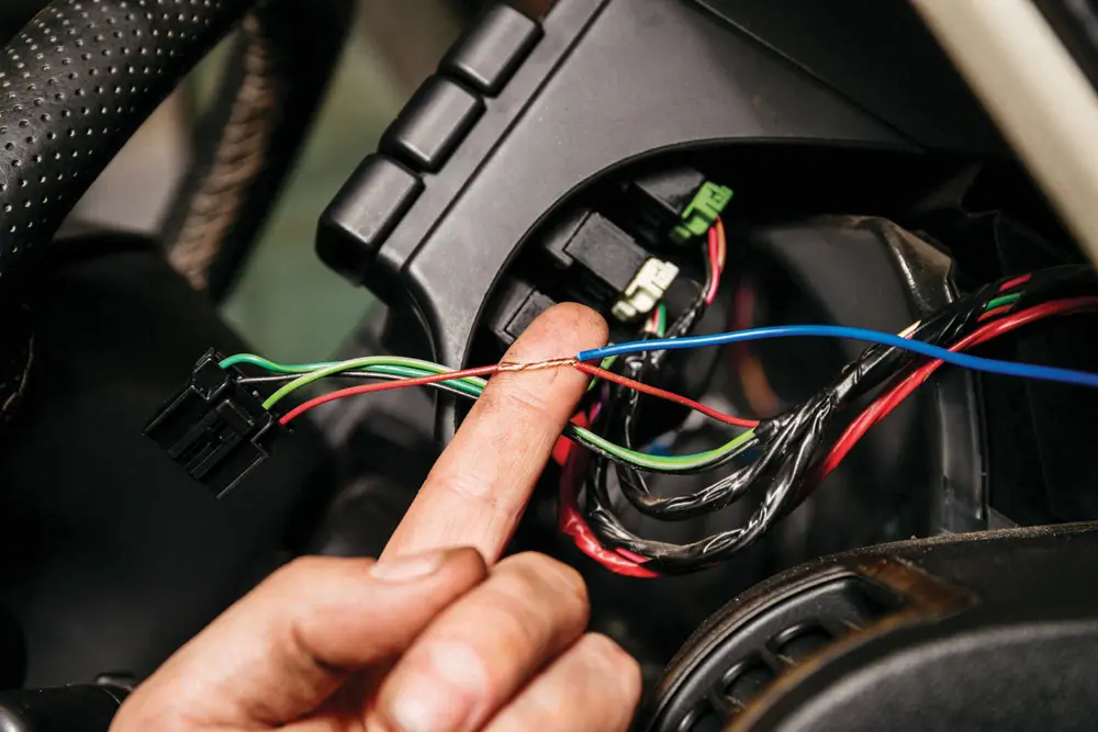
To create a clean splice, tap into the cable for the rear wiper switch illumination. Strip back the insulation carefully, and use a lineman’s twist to securely join the wires together before soldering for a strong electrical connection.
Clean and Secure Joint
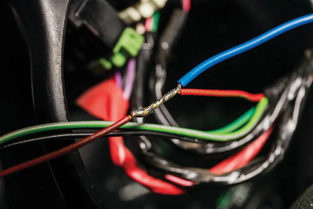
Apply a small amount of solder to create a strong, vibration-resistant joint. Once cooled, insulate the connection properly to prevent movement or chafing. This ensures durability and electrical reliability over time.
Live and Earth Connections
Locate a vacant threaded hole in the body or chassis to bolt down the earth cable securely. For the ignition-live feed, choose a wire running between the fuse box and the ignition switch—this ensures the diff lock system powers up only when the vehicle is on.
Testing the Locking Differential
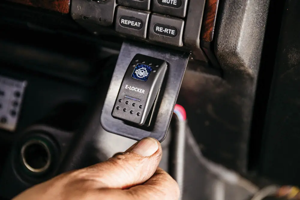
Once wired, the switch should light up with the vehicle’s headlights and receive power with the ignition. To test the locking function, raise one rear wheel and try rotating it by hand with the diff lock engaged—it should not move. Alternatively, engage the locker and drive in a tight circle on loose terrain; you should notice the inner wheel scrubbing, confirming engagement.
Final Thoughts
Installing a locking differential is not a task to take lightly—but the payoff is well worth the effort. With careful attention to detail, proper tools, and a methodical approach, you’ve not only strengthened your vehicle’s off-road capabilities, but also gained a deeper understanding of how it performs under challenging conditions.
From bearing setup to electrical integration, each step plays a crucial role in ensuring the system functions reliably when you need it most. Take the time to test the locker properly, revisit torque settings after initial use, and perform routine checks to keep everything in top shape.
Now that the job’s done, you’re ready to tackle tough terrain with confidence—knowing your traction is no longer left to chance.